N3xxC, hall sensors
Cylindrical rotation speed sensor based on the Hall effect with an electronic unit integrated into the sensor housing. Output: pulse signal 0...30 V, three-wire connection. Compatible with the installation locations of Braun sensors. The maximum operating temperature is up to +125°C.
The sensors consist of a measuring part (a sensitive magnetic element) in an externally threaded housing and a connecting cable. The sensors are connected using cable lugs or a sealed connector mounted on the connecting cable (depending on the design).
The output signal of the sensor is rectangular-shaped and constant-amplitude voltage pulses with a frequency of repetition of the tooth profiles of the control surface.
The sensor is not sensitive to radial shaft impacts.
Typical Datasheet Representation
| Characteristic | Value |
|---|---|
| Measured value | rotation speed |
| Range of measured rotational speeds, Hz | 0...20000 |
| Range of measured rotational speeds with standardized metrological characteristics, Hz | 0,5…17000 |
| Limits of the permissible relative error in measuring the speed of rotation, % | ±0,1 |
| Output signal type | voltage pulse signal proportional to the rotation frequency |
| Type of shaft control surface | gear, groove, key 1) |
| Installation (initial) clearance, mm | 0,5…2,5 2) |
| Overall dimensions of control surface | can be found in the section application |
| Operating temperature range, °С: — sensor element — external electronic assembly |
-40…+125 3) - |
| Output signal range: — lower limit (low level) 0...2.5 V — upper limit (high level) from (Us-2,5) V up to UsV |
0…2,5 В от (Uп — 2,5 В) В до (Uп) В 4) |
| Supply voltage range (Us), V | +10…+30 |
| Current consumption, mA not more than | 20 |
| Maximum operating output current, mA | 20 |
| Current limitation on the output signal, no more than mA — leaking — flowing |
40 100 |
| Short circuit protection at the voltage output, sec | no more than 10 |
| Connection diagram (number of lines) | three-wire |
| Case material | titanium |
| Enclosure protection class according to GOST 14254 | IP67 |
| Sensor cable length range, m | 0,3…10,0 |
| 1) The material of the control surface is ferromagnetic steel. 2) The optimal setting clearance value is selected depending on the size of the control surface and its shape (see the Application section). 3) The maximum temperature of the sensor's electrical connector (for versions with the "ST" code) is not more than +85 °C. 4) Us is the voltage level of the sensor supply; the voltage values are indicated at an output current of no more than 10 mA. |
|
Application
Measuring the speed of rotation, direction of rotation and phase on the main and auxiliary equipment (shafts of steam, gas and hydraulic turbines, turbochargers, centrifugal pumps, Variable Drives ,Pumps , Fans , Conveyors , Generators , Gears , Motors ) with an ambient temperature of no more than
The sensors can be used both independently to measure the speed of rotation, and as part of the automated control system measuring system.
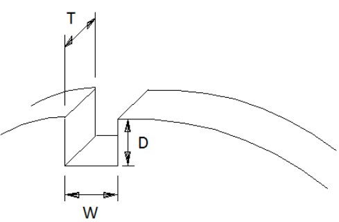
1. For the groove control surface: the ratio of the dimensions of the control surface and the recommended sensor installation clearances:
| Width (W), mm | Depth (D), mm | Thickness (T), mm | Range of installation clearance, mm |
|---|---|---|---|
| not less than 3 | not less than 3 | not less than 5 | from 0,5 to 1,50 |
| not less than 4 | not less than 4 | not less than 6 | from 0,8 to 2,00 |
| not less than 5 | not less than 5 | not less than 7 | from 0,9 to 2,50 |
2. For the gear control surface: if the number of slots (or teeth) is more than one, when selecting the sensor mounting gap, it is also necessary to take into account the gear module (M):
| The gear module (M),*) | Width (W), mm | Range of installation clearance, mm |
|---|---|---|
| from 1 to 1,5 | not less than 3 | from 0,5 to 0,80 |
| from 1,5 to 2 | not less than 3 | from 0,5 to 1,50 |
| from 2 to 4 | not less than 3 | from 0,5 to 2,00 |
| more 4 | not less than 3 | from 0,5 to 2,50 |
Import substitution
Braun type A5S sensor replacement table for N3xxC::
| Braun | Вибробит | Особенности Вибробит1) |
| A5S0DS0M1210B80 | Корпус |
|
| A5S05B90–06 | Корпус |
|
| A5S08T48A2) | Корпус |
|
| A5S09T48 A5S0DD0M2210B48 |
Корпус |
|
| A5S09T94 A5S0DS0M2210В94 |
Корпус |
|
| 1) — Для подключения – кабель удлинительный КУ4/КУ5 (длина от 2) — Корпус М18×1 |
Product Configurator
Overall dimensions and connection diagram
Accessories
Technical documentation
- ВШПА.421412.100.130 РЭ. Датчики частоты вращения Вибробит N. Руководство по эксплуатации
- ВШПА.421412.100.130 ТУ Датчики частоты вращения Вибробит N. Технические условия
- Декларация о соответствии технического регламента ТС 0202011 Электромагнитная совместимость технических средств
- Свидетельство об утверждении типа СИ
- Описание типа СИ
- Методика поверки